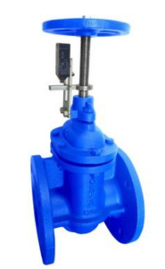
Configuration options

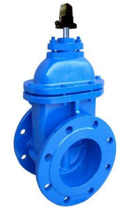
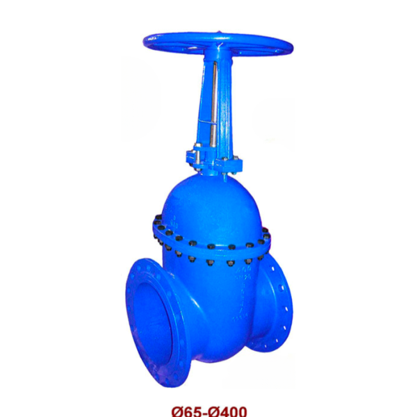
Metal seated gate valve with cap.

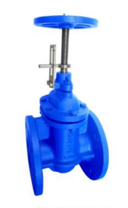
Metal seated gate valve with position indicator.

Metal seated gate valve with 1 limit switch open.

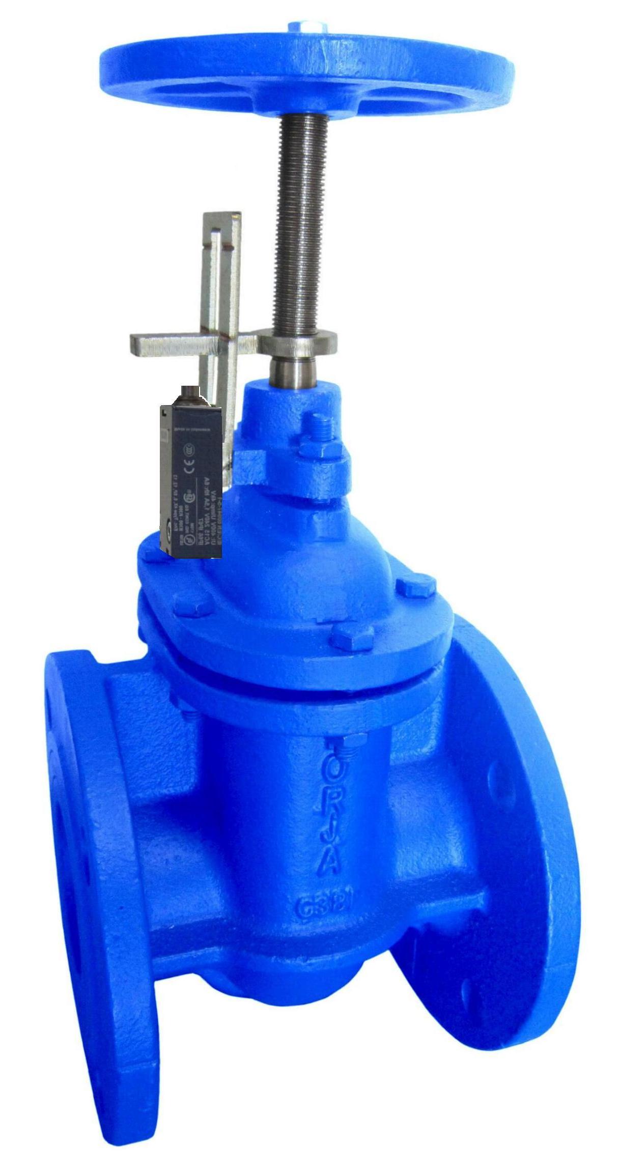
Metal seated gate valve with 1 limit switch closed.

Metal seated gate valve with 2 limit switches.

Metal Seated Gate Valve Fig. 38

– According to EN-1171.
– Face to face dimensions according to EN 558-1 Serie 14. DIN 3202 / F4.
– Flanges dimensions according to UNE-EN 1092-2 PN16.
– Holes dimensions according to UNE-EN 1092-2 PN10 / PN 16.

You must be logged in to download the technical sheet

Product details

Aplications , , , ,
Max. temperature

Aplications

Foot valves are commonly used in ponds, swimming pools, wells and almost anywhere there is a pump.

The surface or opening of the foot valve is larger than that of the pipe, thereby minimizing pressure loss (energy dissipated due to friction along the pipe).

Description

Our metal seated gate valves serve to stop or give complete passage to a fluid, they are bidirectional, and they open and close the circuit using a wedge with a conical design.

They have a concave housing at the bottom of the valve where sediments and impurities from the network are lodged and remain embedded in the wedge and are then released. These will be cleaned during maintenance or repair.

They are suitable for installation in those points where they must remain normally closed because, when the wedge fits into the body, they present good tightness under any circumstance and offer great durability. We will also use them when it comes to handling compressible fluids such as steam so that slow closing does not cause hydraulic phenomena that could damage the valve and the general system.

Packing using Nitrile (NBR) O-rings, which is a good option for materials or fluids made from petroleum. Upon request we have the option of mounting with FKM (Viton®) O-rings resistant to high heat, oil, gasoline, hydrocarbon solvents and climatic conditions (oxygen, ozone and solar rays). Good impermeability to gases and vapor.

They are installed in pipelines as isolation valves. Do not use them as control or regulation valves. To close we will make a rotating movement of the steering wheel clockwise and counterclockwise to open. As these are internal spindle valves, operation is carried out by means of a threaded spindle that does not go up or down, it only rotates and moves a wedge with metal rings up or down along with a spindle nut that is housed in its upper part. .

They are used when a small head loss and total pitch are needed. When it is completely open, it does not usually present an obstruction to the passage of the fluid, which gives a low pressure loss. As they are completely open, the design allows the use of devices to clean the inside of the pipes. The manually operated valve being slow in operation will also avoid the effects of water hammer.