Showing all 10 resultsSorted by average rating
Pipelines of different fluids in the industrial sector
Sort by
Product Category
Maximum Temperature
Product Category
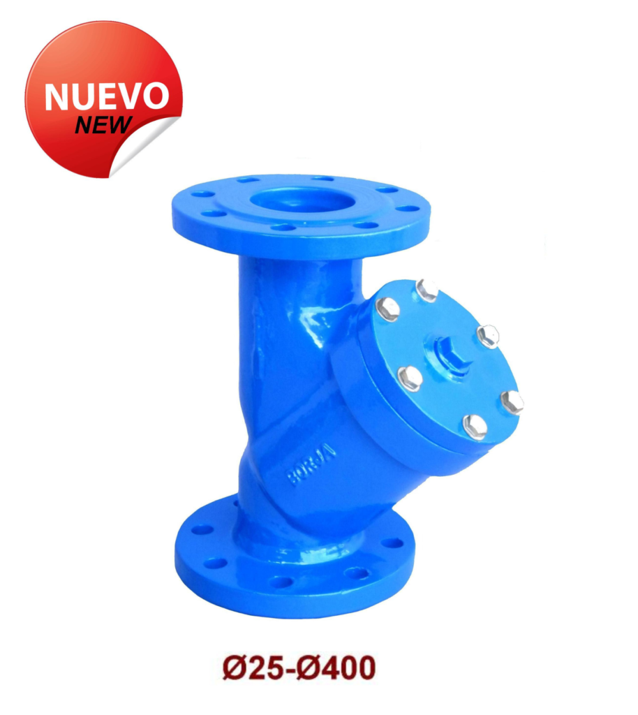
Ductile “Y” type filter with Flanges PN25 Fig.42N
– Mounting length according to EN 558-1 Serie 1. DIN 3202-1 / F1.
– Flange dimensions according to UNE-EN 1092-2 PN25.
– Hole dimensions according to UNE-EN 1092-2 PN25.
OPTIONS:
– Body-lid joint in rubber, cardboard or graphite.
– Different mesh microns in sieve.
– Plugs before and after the sieve to check pressure drop.
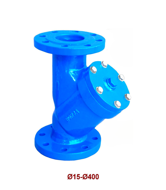
Flanged “Y” Type Strainer (15-400) Fig. 42
– Face to face dimensions according to EN 558-1 Serie 1. DIN 3202-1 / F1.
– Flanges dimensions according to UNE-EN 1092-2 PN16 (From Ø15 to Ø400).
– Flanges dimensions accord. to UNE-EN 1092-2 PN10 or PN16 (From Ø450 to Ø700).
– Holes dimensions according to UNE-EN 1092-2 PN10 / PN16.
OPTIONS:
– Body-bonnet gasket in rubber, carton or graphite.
– Available in any screen perforation.
– Plugs before and after the screen for checking drop pressure.
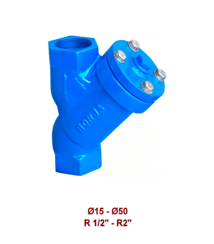
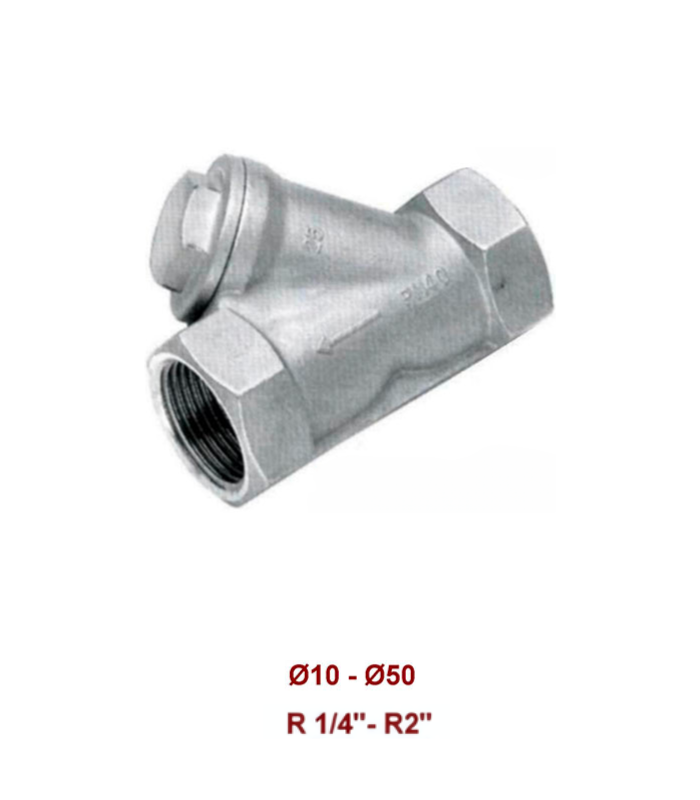
Threaded Ends “Y” Type Strainer Fig 43
Threaded ends according to: DIN 259 / 2999.
OPTIONS:
– Bosy-bonnet gasket in rubber, carton or graphite.
– Available in any screen perforation.
– Plugs before and after the screen for checking drop pressure.
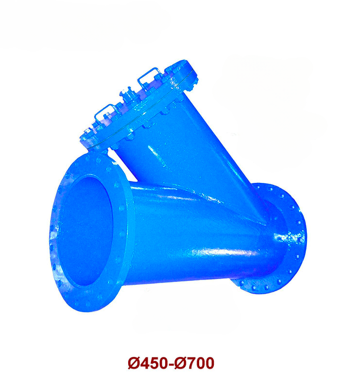
Flanged “Y” Type Strainer (450 – 700) Fig. 42
– Face to face dimensions according to EN 558-1 Serie 1. DIN 3202-1 / F1.
– Flanges dimensions according to UNE-EN 1092-2 PN16 (From Ø15 to Ø400).
– Flanges dimensions accord. to UNE-EN 1092-2 PN10 or PN16 (From Ø.
OPTIONS:
– Body-bonnet gasket in rubber, carton or graphite.
– Available in any screen perforation.
– Plugs before and after the screen for checking drop pressure
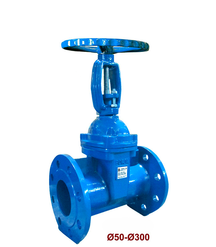
Resilient Seated Gate Valve With NBR/EPDM Rubber Lined Wedge Fig. 55
– EN-1171.
– Face to face dimensions according to EN 558-1 Serie 15. DIN 3202 / F5.
– Flanges dimensions and holes according to UNE-EN 1092-2 PN25.
– Internal and external “ EPOXY “ coating RAL 5017.
– Working conditions NBR: From -1 to +25 bar, from -10 to +80 ºC.
– Working conditions EPDM: From -1 to +25 bar, from -10 to +100 ºC.
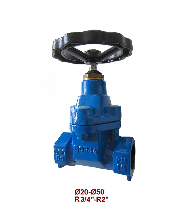
Threaded Ends Gate Valve With Rubber Lined Wedge Fig. 53
– EN-1171.
– Threaded ends according to DIN 259 / 2999.
– Working conditions EPDM: From -1 to +16 bar, from -10 to +100 ºC
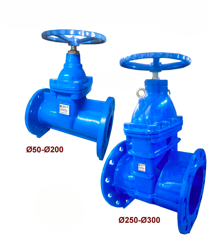
Gate Valve With NBR/EPDM Rubber Lined Wedge Fig. 52
– EN-1071.
– Face to face dimensions according to EN 558-1 Serie 15. DIN 3202 / F5.
– Flanges dimensions and holes according to UNE-EN 1092-2 PN25.
– Working conditions NBR: From -1 to +25 bar, from -10 to +80 ºC.
– Working conditions EPDM: From -1 to +25 bar, from -10 to +100 ºC.
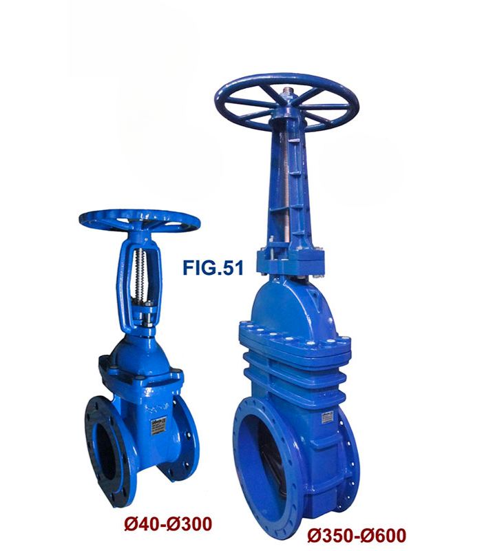
Gate Valve With NBR/EPDM Rubber Lined Wedge Fig. 51
– EN-1171.
– Face to face dimensions according to EN 558-1 Serie 14. DIN 3202 / F4.
– Flanges dimensions according to UNE-EN 1092-2 PN16.
– Holes dimensions according to UNE-EN 1092-2 PN10 / PN 16.
– Internal and external “ EPOXY “ coating RAL 5017.
– Working conditions NBR: From -1 to +16 bar, from -10 to +80 ºC.
– Working conditions EPDM: From -1 to +16 bar, from -10 to +100 ºC.
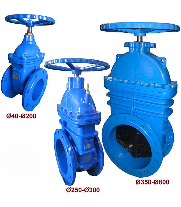
Gate Valve With NBR/EPDM Rubber Lined Wedge Fig. 50
– EN-1071.
– Face to face dimensions according to EN 558-1 Serie 14. DIN 3202 / F4.
– Flanges dimensions according to UNE-EN 1092-2 PN16.
– Holes dimensions according to UNE-EN 1092-2 PN10 / PN 16.
– Working conditions NBR: From -1 to +16 bar, from -10 to +80 ºC.
– Working conditions EPDM: From -1 to +16 bar, from -10 to +100 ºC.


