


Showing 1–12 of 22 results
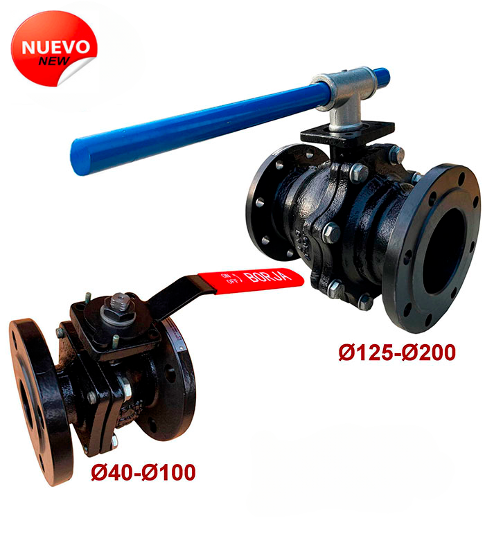
Ball Valve With Flanges Din 3357 Fig. 65B
– Face to face dimensions according to EN 558-1 Serie 27.
– Flanges dimensions and holes according UNE-EN 1092-2 PN16.
CHARACTERISTICS:
It is recommended:
– For driving and cutting service, without strangulation.
– When you need quick opening.
– For temperatures: From -10º to 200 ºC.
– When you need minimal resistance to movement.
Advantages:
– Low cost.
– It cleans by itself.
– Low maintenance.
– Does not require lubrication.
– Compact size.
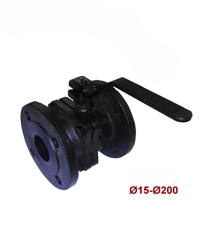
Ball Valve With Flanges Fig. 65
– Face to face dimensions according to EN 558-1 Serial 27.
– Flanges dimensions and holes according UNE-EN 1092-2 PN16.
CHARACTERISTICS:
It is recommended:
– For driving and cutting service, without strangulation.
– When you need quick opening.
– For temperatures: From -10º to 180 ºC.
– When you need minimal resistance to movement.
Advantages:
– Low cost.
– It cleans by itself.
– Low maintenance.
– Does not require lubrication.
– Compact size.
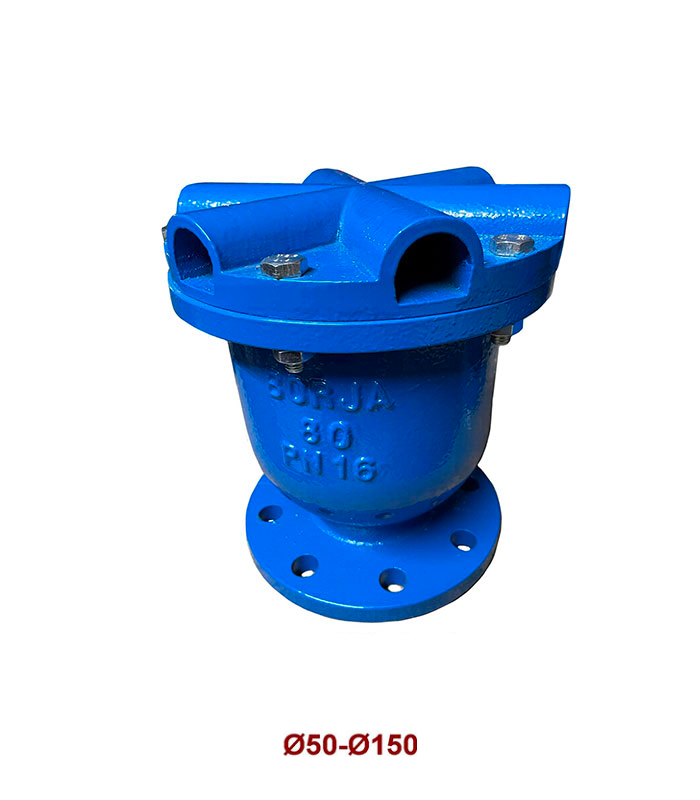
Double Function Air Valve Fig. 27
Flange dimensions and holes according to:
UNE-EN 1092-2 PN10 / PN16.
Globe Valve Fig. 79
- According to EN-13789.
- Face to face dimensions according to EN 558-1 Serie 1. DIN 3202-1 / F1.
- Flanges dimensions and holes according to UNE-EN 1092-2 PN16.
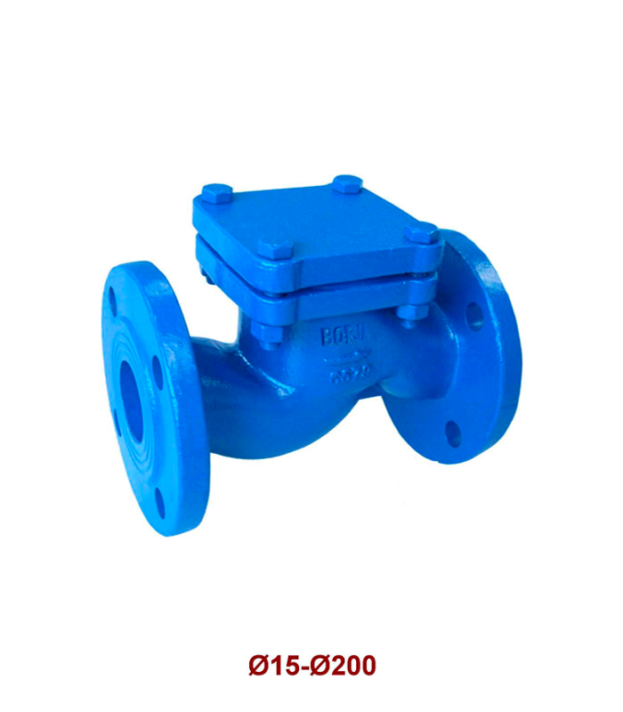
Lift Check Valve Fig. 78
– According to EN-12334.
– Face to face dimensions according to EN 558-1 Serie 1. DIN 3202-1 / F1.
– Flanges dimensions and holes according to UNE-EN 1092-2 PN16.
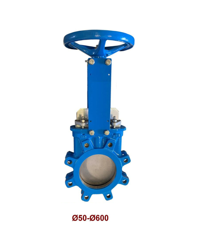
Lug Type Knife Gate Valve Fig. 57 LUG
Joining between flanges according to UNE-EN 1092-2 PN10 or ANSI B16.5 ASA 150 lbs.
Characteristics:
– Monobloc body.
– Full bore: allows a high flow with low head loss.
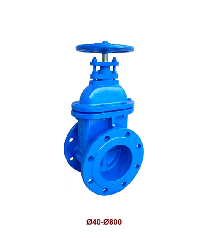
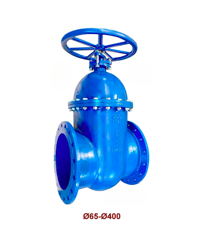
Metal Seated Gate Valve Fig. 31
– According to EN-1171.
– Face to face dimensions according to EN 558-1 Serie 14. DIN 3202 / F4.
– From DN 40 to DN 300, flanges dimensions and holes according to UNE-EN 1092-2 PN10.
– From DN 350 to DN 800, flanges dimensions according to UNE-EN 1092-2 PN16 and holes according to UNE-EN 1092-2 PN10 / PN16.
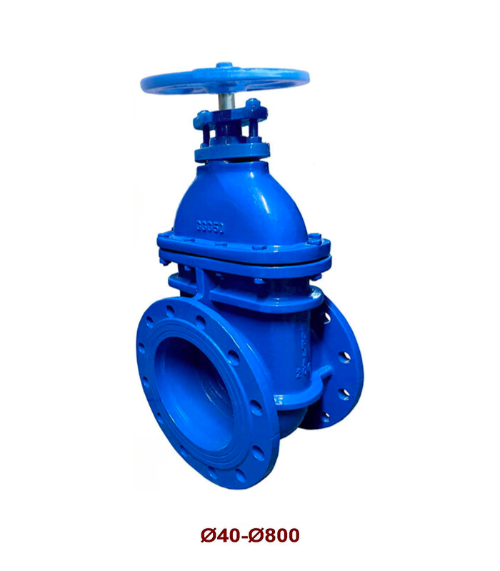
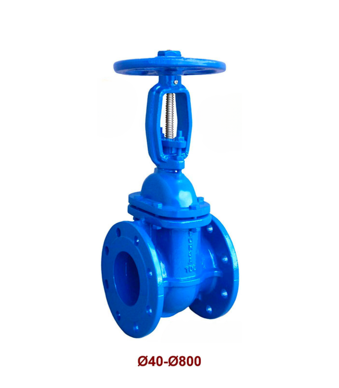
Metal Seated Gate Valve Fig. 31N
– According to EN-1171.
– Face to face dimensions according to EN 558-1 Serie 14. DIN 3202 / F4.
– Flanges dimensions and holes according to UNE-EN 1092-2 PN16.
Metal Seated Gate Valve Fig. 33
– According to EN-1171.
– Face to face dimensions according to EN 558-1 Serie 15. DIN 3202 / F5.
– Flanges dimensions and holes according to UNE-EN 1092-2 PN125.
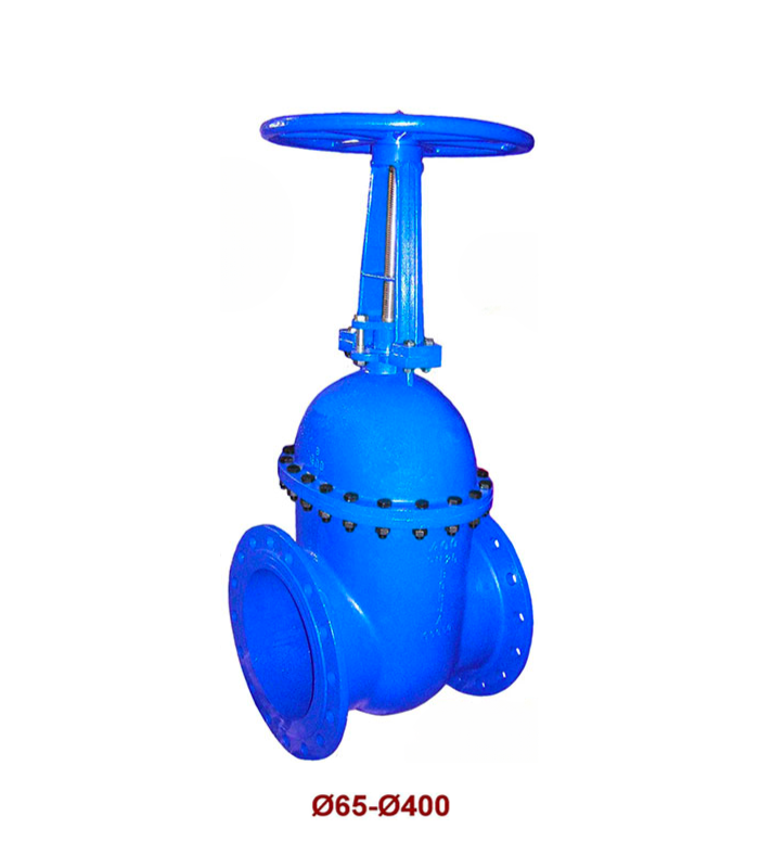
Metal Seated Gate Valve Fig. 34
– According to EN-1171.
– Face to face dimensions according to EN 558-1 Serie 14. DIN 3202 / F4.
– Flanges dimensions according to UNE-EN 1092-2 PN16.
– Holes dimensions according to UNE-EN 1092-2 PN10 / PN16.
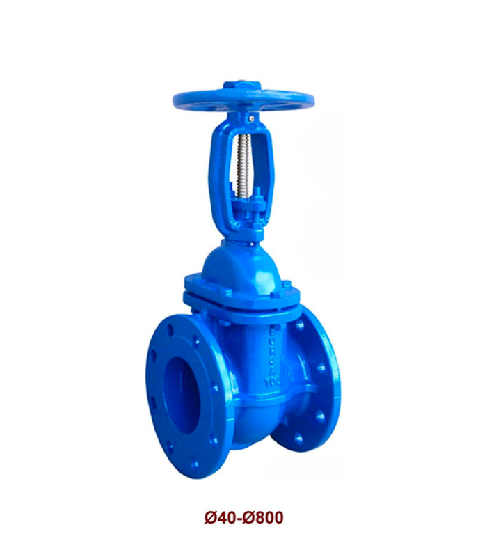
Metal Seated Gate Valve Fig. 34N
– According to EN-1171.
– Face to face dimensions according to EN 558-1 Serie 14. DIN 3202 / F4.
– Flanges dimensions and holes according to UNE-EN 1092-2 PN16.
Metal Seated Gate Valve Fig. 36
– According to EN-1171.
– Face to face dimensions according to EN 558-1 Serie 15. DIN 3202 / F5.
– Flanges dimensions and holes according to UNE-EN 1092-2 PN25.