Showing 1–12 of 15 resultsSorted by popularity
Naval building
Sort by
Product Category
Maximum Temperature
Product Category
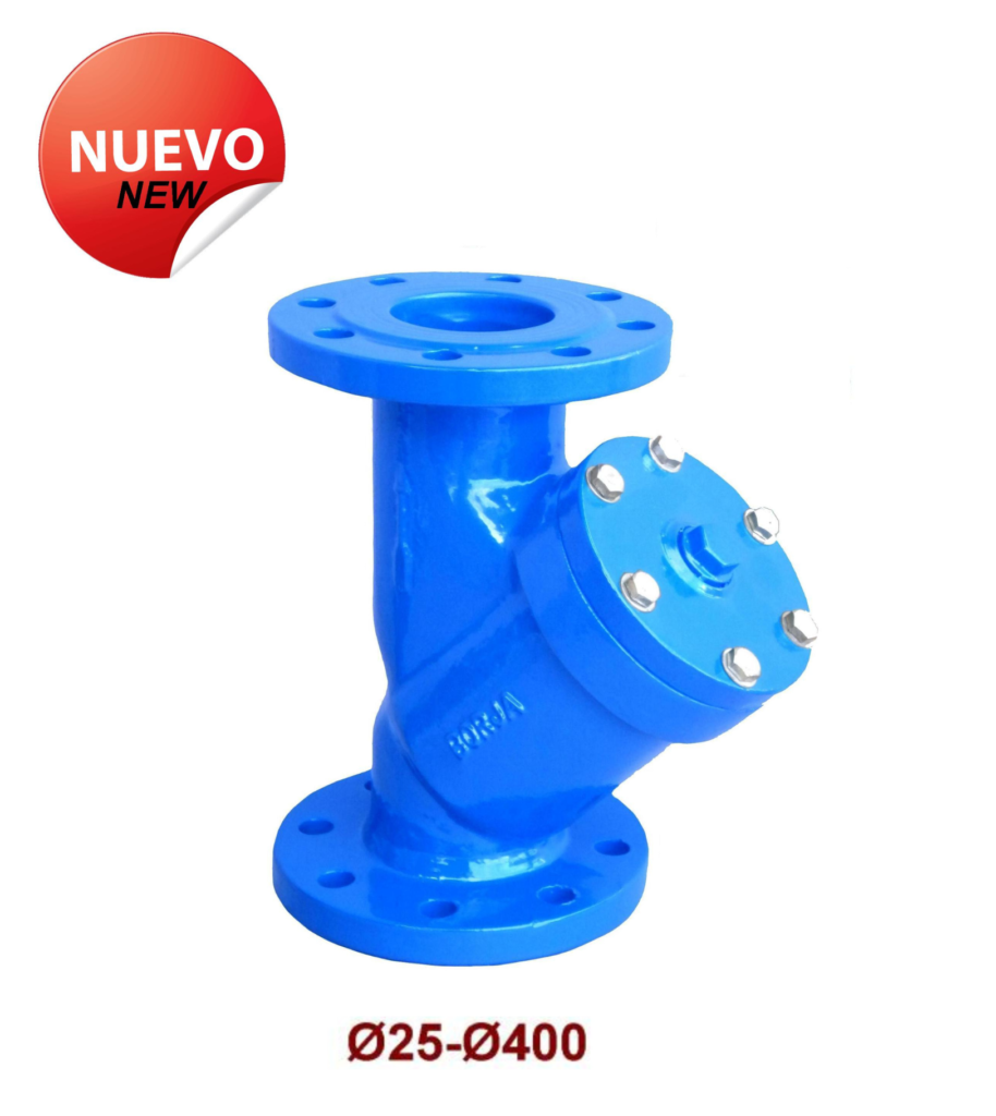
Ductile “Y” type filter with Flanges PN25 Fig.42N
– Mounting length according to EN 558-1 Serie 1. DIN 3202-1 / F1.
– Flange dimensions according to UNE-EN 1092-2 PN25.
– Hole dimensions according to UNE-EN 1092-2 PN25.
OPTIONS:
– Body-lid joint in rubber, cardboard or graphite.
– Different mesh microns in sieve.
– Plugs before and after the sieve to check pressure drop.
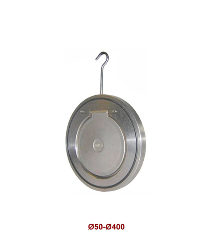
Stainless Steel Anti-Return Disc Check Valve Fig. 19
– According to EN-12334.
– Valve for mounting between flanges according to UNE-EN 1092-2 PN10 / PN16.
– These valves from Ø100 to Ø400 are also valid for mounting between flanges according to ANSI 150 lbs.
CHARACTERISTICS
– Light and robust valve.
– Does not require maintenance.
– Can be mounted horizontally or vertically.
– Easy installation between flanges.
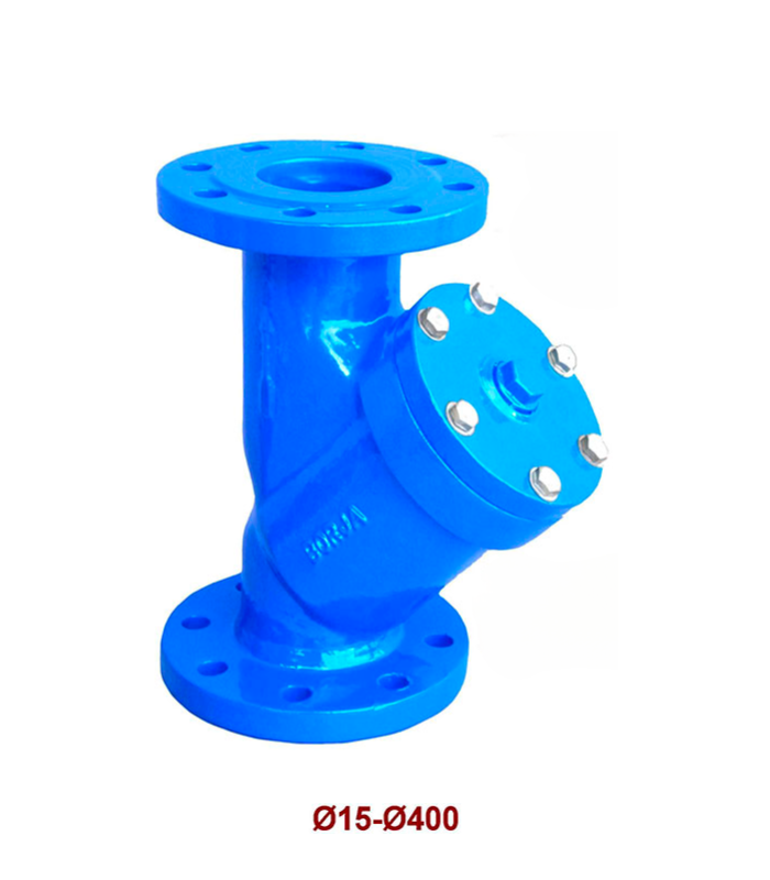
Flanged “Y” Type Strainer (15-400) Fig. 42
– Face to face dimensions according to EN 558-1 Serie 1. DIN 3202-1 / F1.
– Flanges dimensions according to UNE-EN 1092-2 PN16 (From Ø15 to Ø400).
– Flanges dimensions accord. to UNE-EN 1092-2 PN10 or PN16 (From Ø450 to Ø700).
– Holes dimensions according to UNE-EN 1092-2 PN10 / PN16.
OPTIONS:
– Body-bonnet gasket in rubber, carton or graphite.
– Available in any screen perforation.
– Plugs before and after the screen for checking drop pressure.
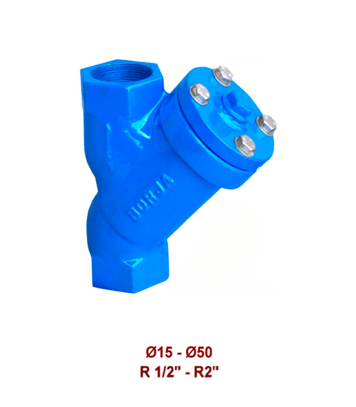
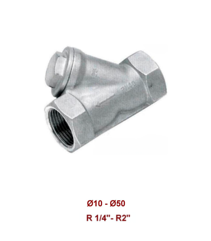
Threaded Ends “Y” Type Strainer Fig 43
Threaded ends according to: DIN 259 / 2999.
OPTIONS:
– Bosy-bonnet gasket in rubber, carton or graphite.
– Available in any screen perforation.
– Plugs before and after the screen for checking drop pressure.
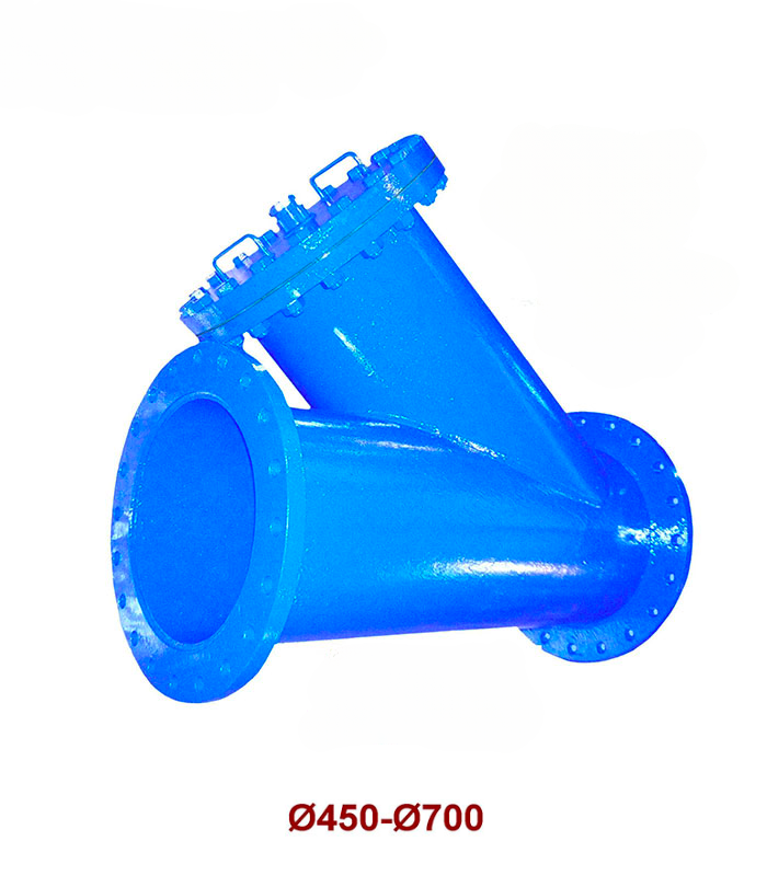
Flanged “Y” Type Strainer (450 – 700) Fig. 42
– Face to face dimensions according to EN 558-1 Serie 1. DIN 3202-1 / F1.
– Flanges dimensions according to UNE-EN 1092-2 PN16 (From Ø15 to Ø400).
– Flanges dimensions accord. to UNE-EN 1092-2 PN10 or PN16 (From Ø.
OPTIONS:
– Body-bonnet gasket in rubber, carton or graphite.
– Available in any screen perforation.
– Plugs before and after the screen for checking drop pressure
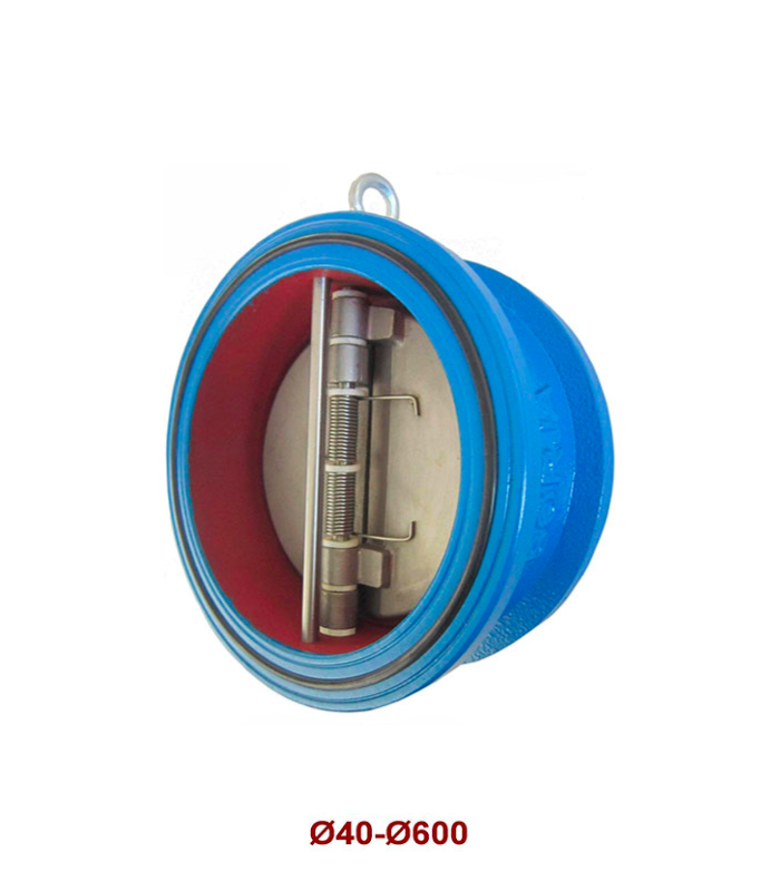
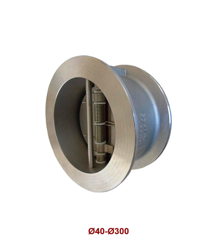
Double Disk Check Valve Fig. 37
– According to EN-12334.
– Face to face dimensions according to EN 558-1 Serie 16. API 609.
– Valve for mounting between flanges according to UNE-EN 1092-2 PN10 / PN16.
– These valves from Ø100 to Ø600 are also suitable for mounting between flanges according to ANSI Class 150 lbs.
CHARACTERISTICS:
– Double disk and seat design for optimum sealing.
– Springs with elongated and curved supports that offer a longer life.
– Minimal wear of the seat and disks.
– Excellent work in various mounting orientations.
– It has a low maintenance cost.
– Minimum weight and compact design, can reduce weight on the line.
– Ideal for installation in vertical pipes.
– It has an easy installation and removal.
– Eye bolt available between size Ø125 to Ø600 to facilitate the centering and assembly of the valve.
PN25 Double Disk Check Valve Fig. 37
– According to EN-12334.
– Face to face dimensions according to EN 558-1 Serie 16. API 609.
– Valve for mounting between flanges according to UNE-EN 1092-2 PN25
CHARACTERISTICS:
– Double disk and seat design for optimum sealing.
– Springs with elongated and curved supports that offer a longer life.
– Minimal wear of the seat and disks.
– Excellent work in various mounting orientations.
– It has a low maintenance cost.
– Its minimum weight and compact design can reduce weight on the line.
– Ideal for installation in vertical pipes.
– It has an easy installation and removal.
– Eye bolt available between size Ø250 to Ø600 to facilitate the centering and
assembly of the valve.
Stainless Steel Double Disk Check Valve Fig. 37
– According to EN-12334.
– Face to face dimensions according to EN 558-1 Serie 16. API 609.
– Valve for mounting between flanges according to UNE-EN 1092-2 PN10 / PN16.
– These valves from Ø100 to Ø600 are also suitable for mounting between flanges according to ANSI Class 150 lbs.
CHARACTERISTICS:
– Double disk and seat design for optimum sealing.
– Springs with elongated and curved supports that offer a longer life.
– Minimal wear of the seat and disks.
– Excellent work in various mounting orientations.
– It has a low maintenance cost.
– Minimum weight and compact design, can reduce weight on the line.
– Ideal for installation in vertical pipes.
– It has an easy installation and removal.
– Eye bolt available between size Ø125 to Ø600 to facilitate the centering and
assembly of the valve.
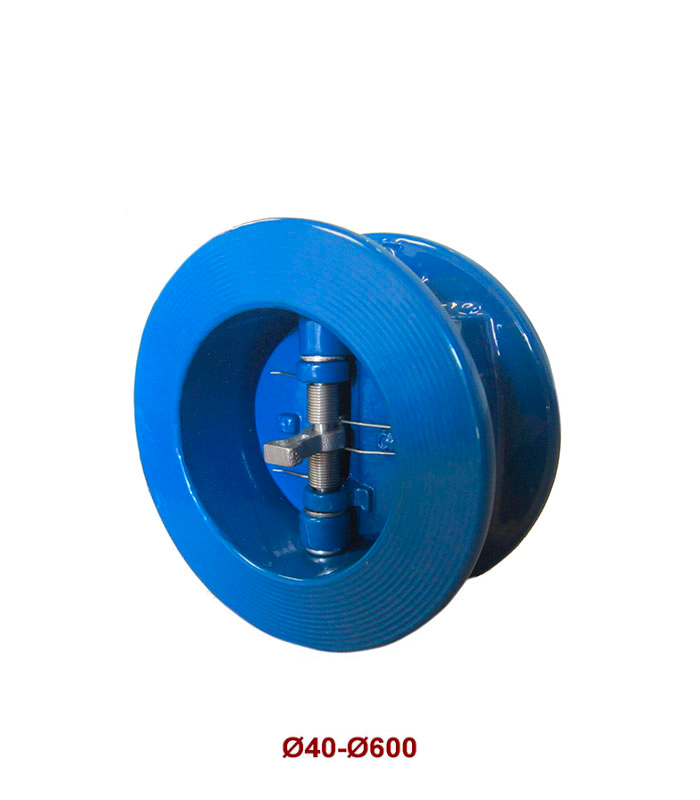
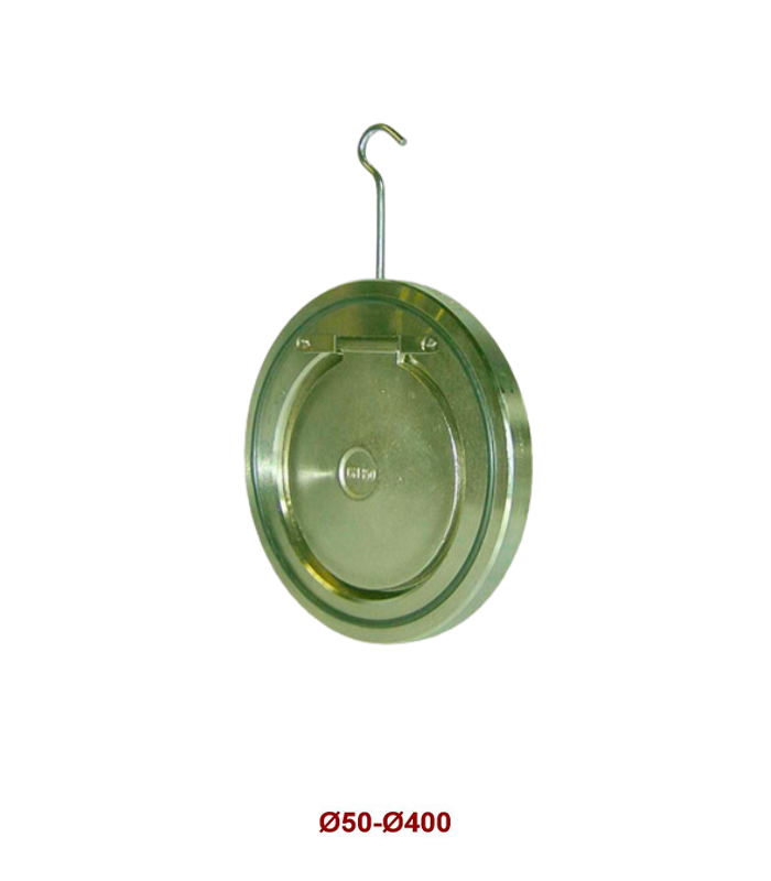
Disk Check Valve Fig. 19
– According to EN-12334.
– Valve for mounting between flanges according to UNE-EN 1092-2 PN10 / PN16.
– These valves from Ø100 to Ø400 are also suitable for mounting between flanges according to ANSI Class 150 lbs.
CHARACTERISTICS:
– Strong valve, reduced weight and dimension.
– It doesn’t need maintenance.
– For horizontal or vertical working position.
– Easy assembly between flanges.
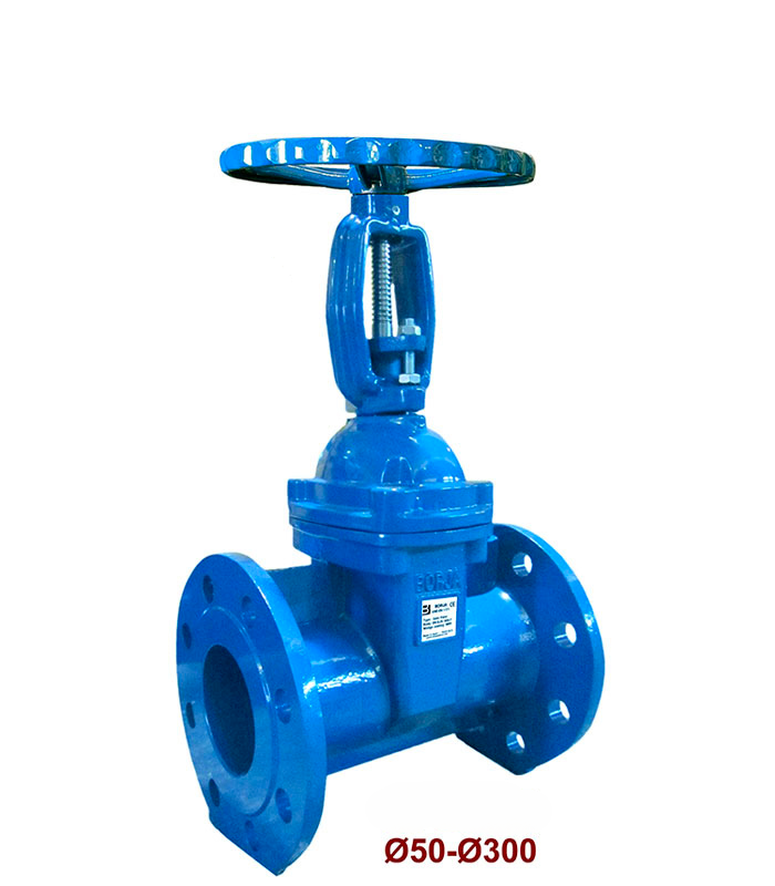
Resilient Seated Gate Valve With NBR/EPDM Rubber Lined Wedge Fig. 55
– EN-1171.
– Face to face dimensions according to EN 558-1 Serie 15. DIN 3202 / F5.
– Flanges dimensions and holes according to UNE-EN 1092-2 PN25.
– Internal and external “ EPOXY “ coating RAL 5017.
– Working conditions NBR: From -1 to +25 bar, from -10 to +80 ºC.
– Working conditions EPDM: From -1 to +25 bar, from -10 to +100 ºC.
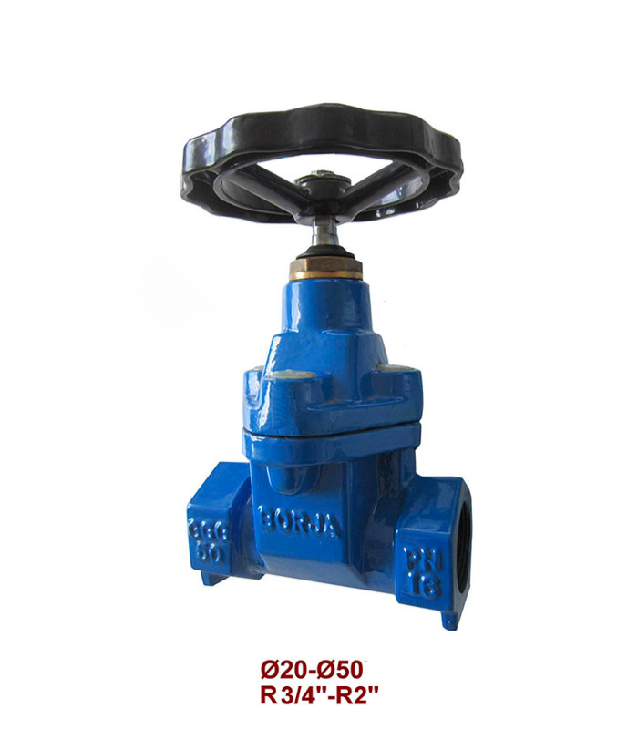
Threaded Ends Gate Valve With Rubber Lined Wedge Fig. 53
– EN-1171.
– Threaded ends according to DIN 259 / 2999.
– Working conditions EPDM: From -1 to +16 bar, from -10 to +100 ºC


